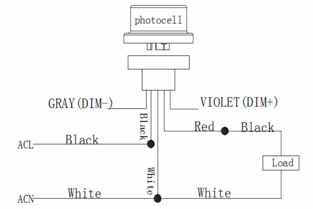
Ge 3480v0610d Pump Control Box Wiring Diagram
3Ø WIRING DIAGRAMS 1Ø WIRING DIAGRAMS Diagram ER9 M 3 1 5 9 3 7 11 Low Speed High Speed U1 V1 W1 W2 U2 V2 TK TK Thermal Overloads TWO SPEED STARDELTA MOTOR Switch M 3 0-10V 20V 415V AC 4-20mA Outp uts Diagram IC2 M 1 240V AC 0-10V Outp ut Diagram IC3 M 1 0-10V 4-20mA 240V AC Outp uts These diagrams are current at the time of publication. To replace the two wire pump.
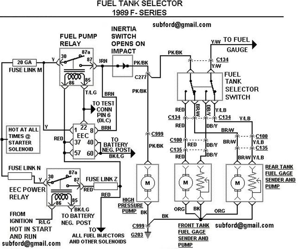
 Eec Wiring Diagram Mustang Fuse Diagrams Volvo 740 Wiring Diagram 1991 For Wiring Diagram Schematics
Heat Pump Thermostat Wiring Chart Diagram - HVAC - The following graphics are meant as a guide only.

Ge 3480v0610d pump control box wiring diagram. The above diagram is a complete method of single phase motor wiring with circuit breaker and contactor. Room thermostat installation wiring guide. If you cannot locate your wiring diagram you can call the Appliances Answer Center with your complete model number.
Star-Delta Y-Δ 3-phase Motor Starting Method by Automatic star-delta starter with Timer. There are a couple of ways to find the part or diagram you need. Each component ought to be placed and linked to different parts in particular manner.
Single Phase Marathon Motor Wiring Diagram Gallery. The diagram may be mailed or e-mailed. Lets start with the most basic float switch.
This article gives a table showing the proper wire connections for the American Standard GE or Trane room thermostat used to control heating or air conditioning equipment. A two-wire single-pole single-throw float switchThe rising action of the float can either close ie turn on a Normally Open circuit or it can open turn off a Normally Closed circuitInstallation scenarios might include a Normally Open float switch turning on a pump to empty a tank Control Schematic 2 or a Normally Closed. Marathon Electric Motor Wiring Diagram - Collections Of Wiring Diagram for Electric Motor with Capacitor Inspirationa New.
Boat Lift Switch Wiring Diagram wiring diagram is a simplified agreeable pictorial representation of an electrical circuitIt shows the components of the circuit as simplified shapes and the capability and signal friends amid the devices. Assortment of ge dryer wiring diagram. Always follow manufacturers instructions for both the thermostat and the HVAC system.
Wiring Diagram Pool Pump Motor Best Pool Pump Wiring Diagram. Some window air conditioners dehumidifiers compact refrigerators and small countertop microwaves do not have wiring diagrams. Marathon Trailer Wiring Diagram Inspirationa Wiring Diagram Marathon.
It shows the parts of the circuit as streamlined forms as well as the power as well as signal links in between the tools. In the search box below enter all or part of the part number or the parts name. The green ground wire should also be terminated to the box and a ground coming from the panel.
The diagrams for both the two and three wire pumps can be downloaded using Adobe. After determining the voltage is zero disconnect the motor wires directly from the pressure switch box M1 and M2. Wire Data102 Electrical Formulas103-104 List of Tables Table 1 Standard Elementary Diagram Symbols 1 Table 2 NEMA and IEC Terminal Markings 4 Table 3 NEMA and IEC Controller Markings and Elementary Diagrams 4 Table 4 Control and Power Connections for Across-the-Line Starters 600 V or less4 Table 5 Motor Lead Connections 64.
Three Phase Motor Connection STARDELTA Without Timer Power Control Diagrams. Single Phase Motor Wiring Diagram With Capacitor baldor single phase motor wiring diagram with capacitor single phase fan motor wiring diagram with capacitor single phase motor connection diagram with capacitor Every electrical arrangement is made up of various unique pieces. A wiring diagram is a simplified traditional photographic depiction of an electric circuit.
Additional articles on this site concerning thermostats and wiring can help you solve your problem or correctly wire a new thermostat. You can reach us by dialing 1. Three Phase Motor Connection Schematic Power and Control Wiring Installation Diagrams.
This article series explains the basics of wiring connections at the thermostat for heating heat pump or air conditioning systems. Click a diagram to see the parts shown on that diagram. In the above one phase motor wiring i first connect a 2 pole circuit breaker and after that i connect the supply to motor starter and then i do cont actor coil wiring with Normally Close push button switch and Normally Open push button switch and in last i do connection between capacitor.
Not all parts are shown on the diagramsthose parts are labeled NI for not illustrated.
 Diagram Wiring Diagram Zinsco Full Version Hd Quality Diagram Zinsco Diagramrt Hosteria87 It
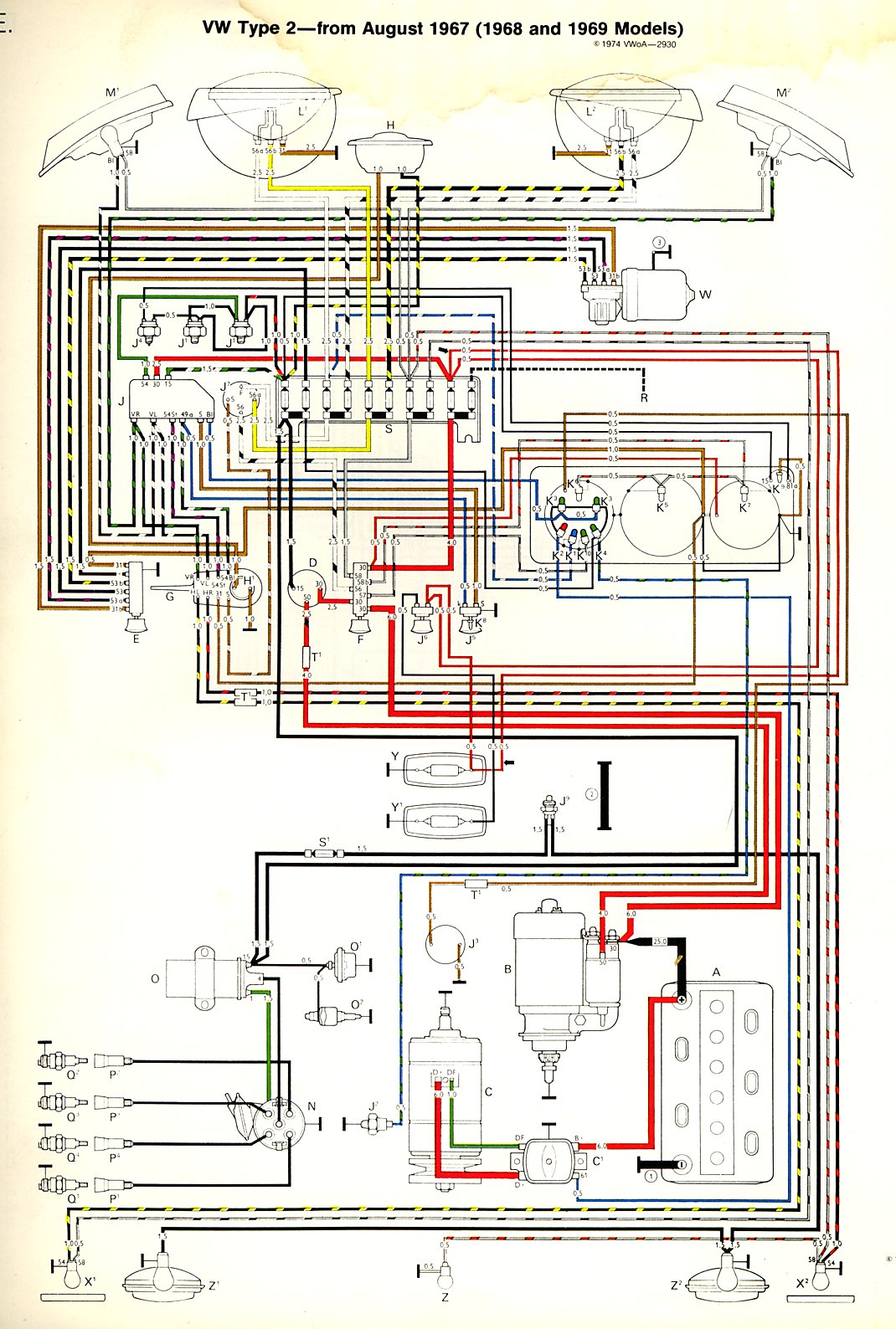
 Engine Diagram 1974 Vw Bus Camper Ge 3480v0610d Pump Control Box Wiring Diagram Light Switch Tukune Jeanjaures37 Fr
 Ge Electric Motor Wiring Diagram And Ge Ac Wiring Diagram Wiring Diagram Ac Wiring Thermostat Wiring Circuit Diagram
 17 Compressor Capacitor Wiring Diagram Electrical Circuit Diagram Ac Wiring Ac Capacitor


